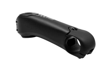
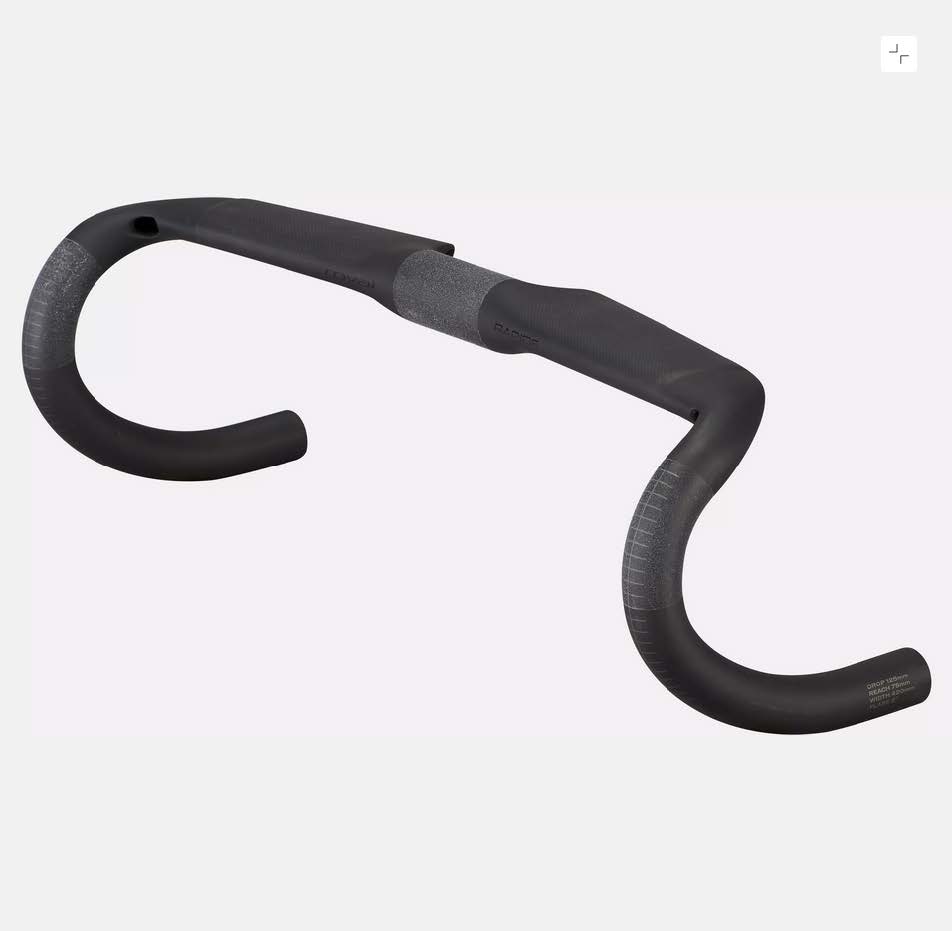
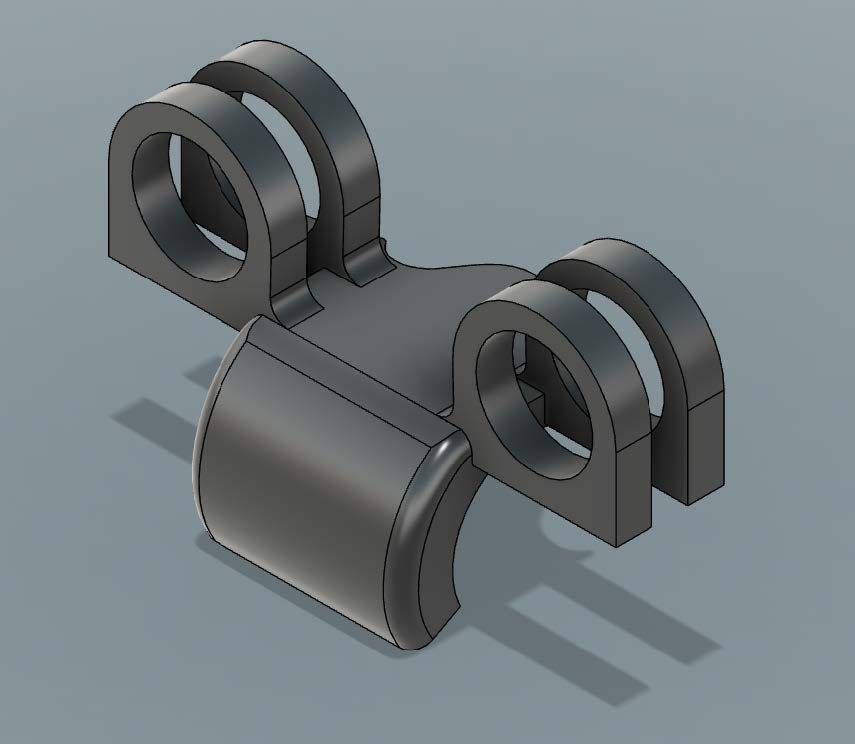
This class project for a Finite Element Analysis (FEA) course focused on redesigning the ENVE Aero Stem to work with standard 30 mm clip-on aerobars, such as the Zipp Vuka Clip. With flat aero handlebars becoming increasingly popular, the goal was to offer cyclists a simple solution that didn’t require replacing their entire cockpit. This idea was sparked when a teammate struggled to find a compatible setup before an Ironman and ultimately raced without aerobars.
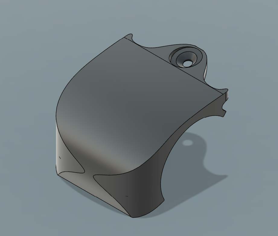
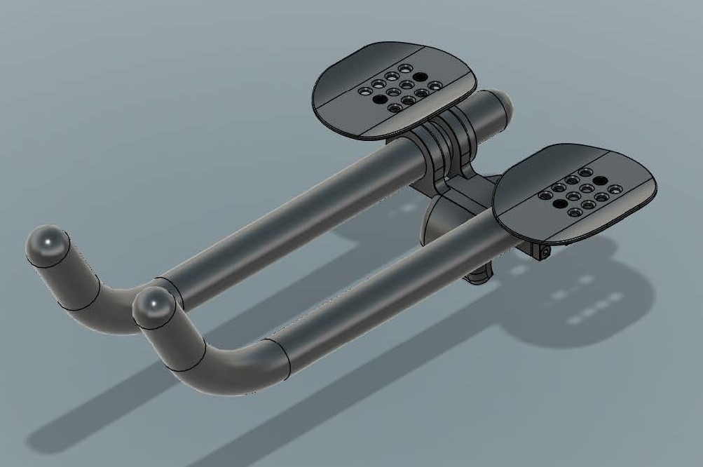
The ENVE Aero Stem poses unique challenges for mounting clip-on aerobars due to its non-standard three-point mounting design and incompatibility with traditional round handlebar aerobars. The primary objective of this project was to design and evaluate a secure mounting solution for aerobars. By focusing on the faceplate redesign, the analysis aimed to ensure the attachment meets structural and safety requirements, identify stress concentration areas, and calculate deformation under typical loads. The redesign allows cyclists who already have the ENVE Aero Stem to adapt their system instead of fully replacing their cockpit.
The original ENVE Aero Stem and faceplate geometry were created in Fusion 360. New aerobar attachment components were added to achieve the desired aero setup. The model was then simplified for analysis by removing small, non-critical features such as bolts and fillets. These simplifications facilitated meshing and removed bodies that could introduce simulation errors.
Standard quadratic tetrahedral (C3D10) elements were selected for meshing due to their ability to accurately represent complex geometries and capture stress gradients. Element sizes were iteratively refined, with the finest mesh comprising ~736,575 degrees of freedom (DoF). Partitioned meshes allowed critical regions to use a finer seed size while keeping total nodes under Abaqus limits.
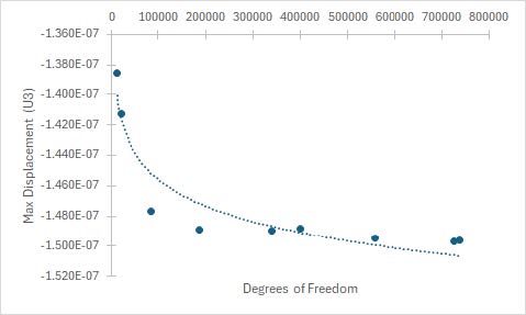
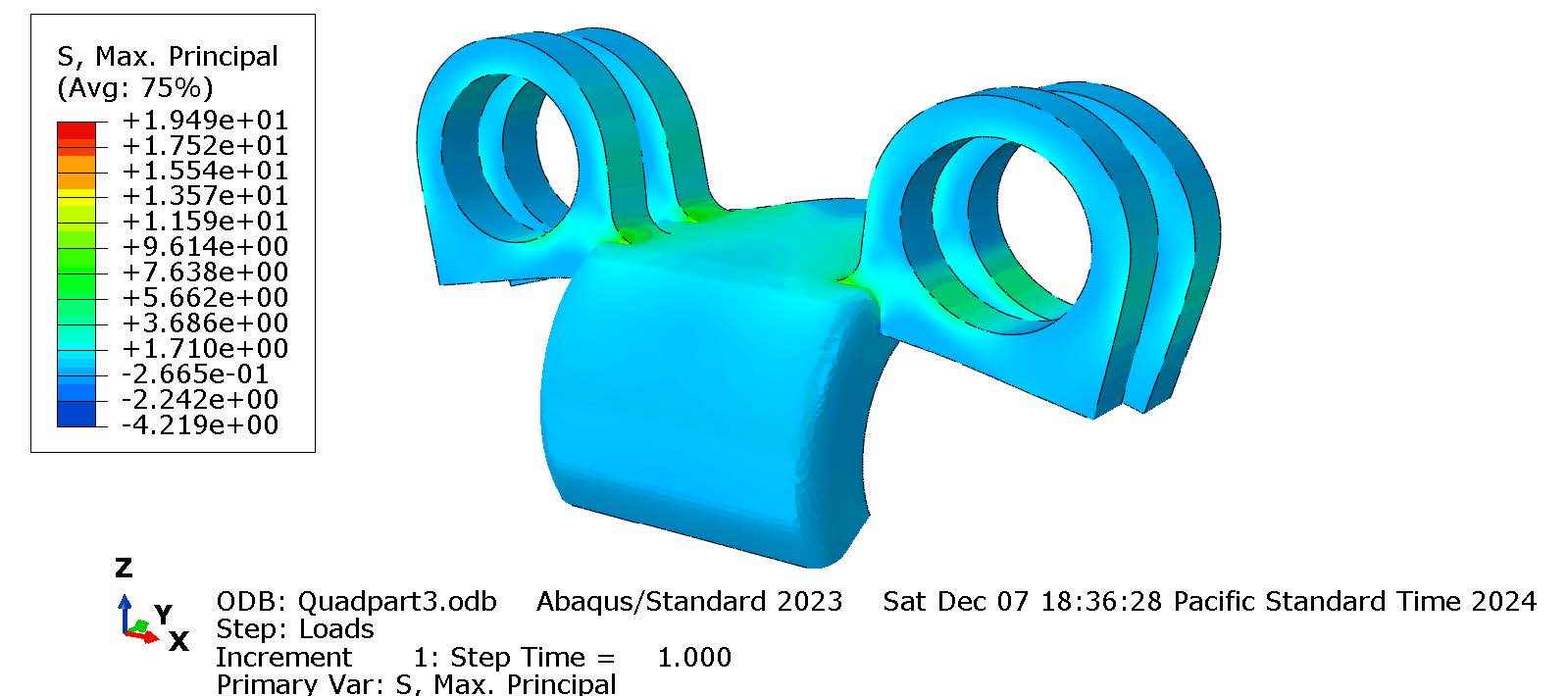
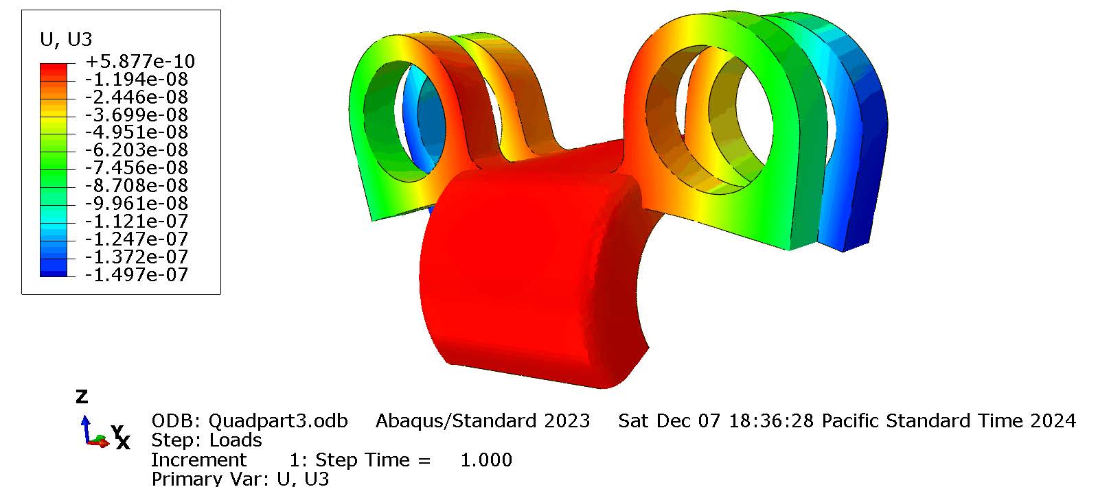
A linear static analysis was performed to assess stress and deformation under typical cycling loads. Maximum stresses were observed at the interface between the aerobars and the faceplate but remained below the material's yield strength, confirming structural integrity. Displacement results were within acceptable limits, ensuring functionality and safety. Convergence was achieved as displacement (ΔU3) and stress stabilized with increasing degrees of freedom, confirming the mesh's accuracy. The only warning related to distorted elements in the set WarnElemDistorted, but were very few and had minimal impact on overall results. Despite simplifications, the analysis provided key insights into the design's performance and confirmed the faceplate's suitability for the intended application. The FEA revealed a maximum principal stress of 23.2 MPa at node 41103, significantly lower than the hand calculation prediction of 75.11 MPa. Hand calculations overestimate stresses due to simplified assumptions, while FEA accounts for complex geometry and load distribution.
Table 1: Degrees of Freedom, Maximum Displacement, and Stress Values at Different Mesh Refinements
| DOF | U3 (@ Node: 113904) | Max Principal Stress (@ Node: 41103) | Seed |
|---|---|---|---|
| 11,538 | -1.38E-07 | 11.64 MPa | 8 |
| 20,658 | -1.41E-07 | 8.086 MPa | 5 |
| 86,127 | -1.47E-07 | 12.19 MPa | 2.5 |
| 186,354 | -1.48E-07 | 12.10 MPa | 1.875 |
| 339,489 | -1.49E-07 | 23.2 MPa | Partition 2 |
| 400,155 | -1.48E-07 | 11.60 MPa | Partition 1 |
| 556,260 | -1.49E-07 | 19.71 MPa | 1.25 |
| 725,154 | -1.49E-07 | 19.49 MPa | Partition 3 |
| 736,575 | -1.49E-07 | 20.13 MPa | 1.1 |
The primary goal of this project was to redesign the ENVE Aero Stem faceplate for compatibility with clip-on aerobars while ensuring its structural integrity under realistic loading conditions. The FEA results confirmed that the redesigned faceplate maintains stresses well below the yield strength of aluminum and exhibits minimal deformation, indicating its ability to safely withstand typical cycling forces. While discrepancies between FEA and hand calculations were observed—most notably, a maximum stress of 23.2 MPa from FEA compared to 75.11 MPa from hand calculations, and a displacement of -1.49 × 10^-7 m versus 0.0003526 m, these differences are not surprising. The hand calculations relied on very significantly simplified assumptions and idealized conditions, which often overestimate stress and deformation, whereas the FEA offered a more nuanced analysis, albeit with some modeling simplifications. While the current model demonstrates the feasibility of the redesigned faceplate, refining the analysis could enhance its accuracy and applicability. Future work should focus on incorporating detailed bolt connections, more accurate boundary conditions, and less geometric simplification to better capture real-world performance. Additionally, exploring dynamic loading scenarios such as road vibrations and impacts would provide a more comprehensive assessment of the design’s durability. Despite these limitations, the results indicate that the redesigned faceplate is a robust and functional solution, meeting the project's objectives and offering a solid foundation for further optimization and testing.
Table 2: Comparison between Simulation and Hand Calculation Results
| Parameter | Simulation Result | Hand Calculation | Difference |
|---|---|---|---|
| Max Stress (MPa) | 23.2 | 75.11 | Significant |
| Max Displacement (m) | -1.49×10^-7 | 3.526×10^-4 | Significant |
This project successfully redesigned the ENVE Aero Stem faceplate to accommodate clip-on aerobars, addressing a critical limitation of the original design. Using FEA, we demonstrated that the redesigned faceplate meets structural integrity and safety requirements, with stresses below material yield strength and minimal deformation under expected loads. Stress and deformation results from FEA closely align with hand calculations, validating the simulation. Although limitations such as simplified bolt modeling were present, the analysis provides a strong foundation for the faceplate’s feasibility and functionality. Future improvements, including dynamic loading analyses and material optimizations, could further enhance the design’s performance and applicability.
Files
The reports that I wrote for the class is attached here: